Pacific Rim Wastewater Solutions Ltd. logo

Projects

Recent Projects

These are real onsite sewerage systems designed, filed and commissioned by Jordan Huscroft, P.Geo., on Vancouver Island — steep half-acre lakeside lots, a setback departure beside a drinking-water lake, a dispersal bed built into a terraced rock slope, and a commercial system on a boat-access resort. Every one is a custom design built to fit the property it sits on, rather than a catalogue system dropped onto a site that will not carry it. Client names and addresses are deliberately withheld.

Why you will not find an address on this page

Every project below is real, and every technical figure is taken from the project record rather than written for effect. What is missing is deliberate: no client names, no civic addresses, no legal descriptions, no coordinates and no fees. Locations are generalised to a district, and photographs are published only where nothing in the frame identifies the property or the people on it.

Your septic design says a great deal about your property. It is treated as your information, not marketing material.

What do these projects have in common?

Constrained sites. Each began with test pits and measurements, and each needed analysis — mounding calculations, mass-loading screens, field decisions during construction. They were all designed either to be compliant with the Standard Practice Manual, or to meet site-specific target objectives where the manual had to be departed from.

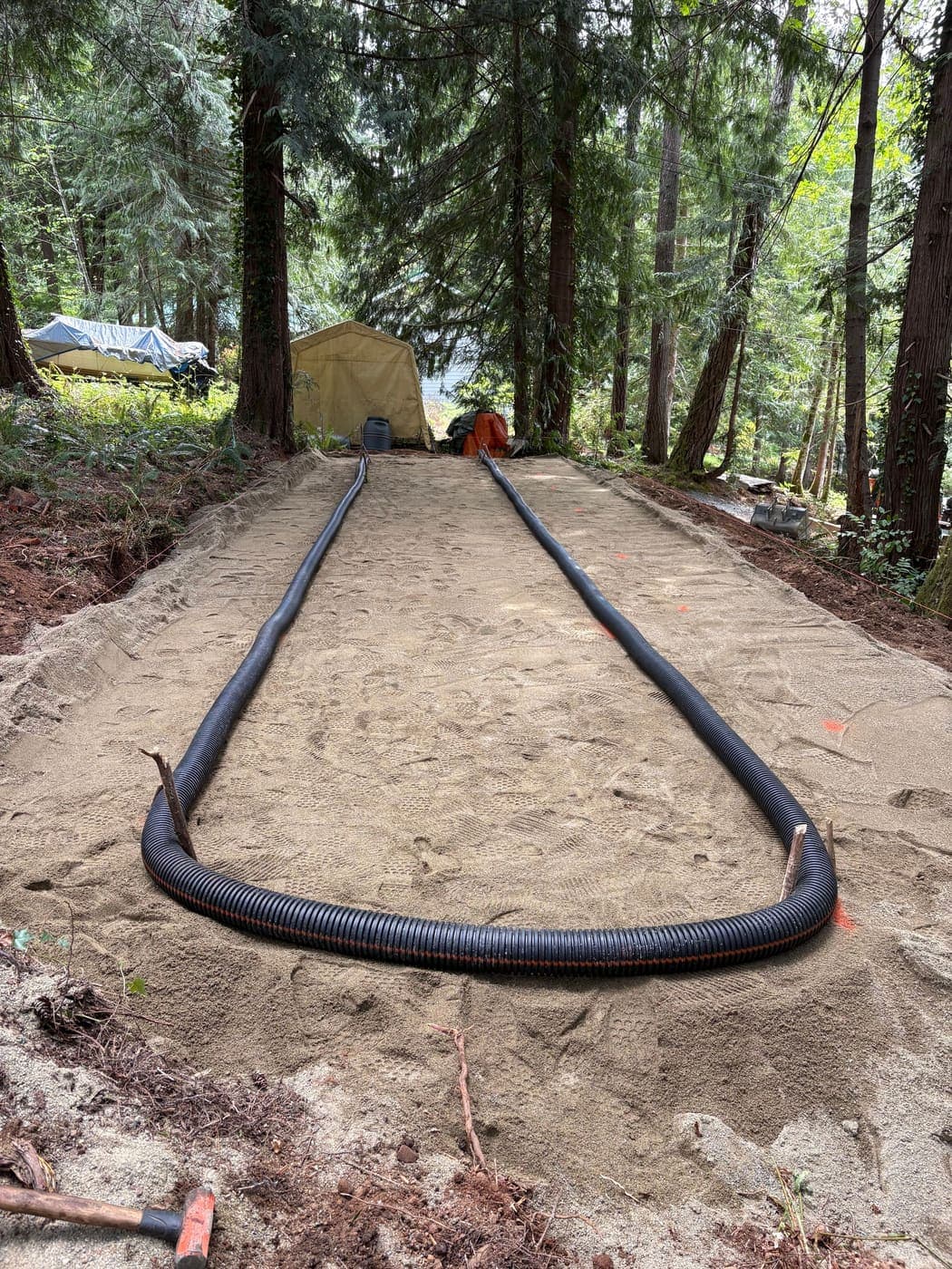
Sand lined seepage bed under construction, showing the levelled specification sand layer with two black perforated passive vent runs laid along the outside edges

Project 01

Sand lined bed replacement on a steep half-acre lakeside lot

Location
Sproat Lake area, rural Alberni Valley
System type
Type 1 sand lined bed, micro-time-dosed pressure distribution
Timeline
Filing report issued early January 2026; field commissioning in May 2026.

A dated, undersized system served a three-bedroom home with a new two-bedroom suite on a lot under half an acre, sloping roughly 20 per cent toward the lake the household also draws its drinking water from. There was no room for a conventionally sized dispersal bed. The replacement is a micro-time-dosed sand lined bed, sized by hydrogeological analysis instead of by rule of thumb.

What made this site difficult?

  • Design flow of 2,300 L/day from two dwelling units — a three-bedroom house plus a newly added two-bedroom suite — on a 0.45-acre lot that leaves very little usable dispersal footprint once setbacks are honoured.
  • About 20 per cent slope falling toward the lake, which is also the property's potable water source.
  • Site constraints capped the bed at 14 m long. At that length the linear loading rate lands near 165 L/day/m, roughly double the 80 L/day/m the standard practice manual would ordinarily point to.
  • The bed footprint the site allowed exceeds the 3 m maximum width the Standard Practice Manual provides for, so ventilation of the infiltrative surface had to be solved deliberately rather than assumed.

How was it solved?

  • Test pits found 95 cm of friable, granular sandy loam with no mottling — seasonal high water table deeper than the deepest pit. Three permeameter tests returned a median field-saturated conductivity of 438 mm/day (range 355–473).
  • Rather than accept the short bed on faith, the higher linear loading rate was justified with Darcy and Payne & Ralston water-table-mounding analysis: predicted maximum mounding 47 cm above the seasonal high water table, leaving 48–68 cm of excess vertical separation.
  • Micro-timed dosing applies the daily flow in many small doses rather than a few large ones — 28 doses per day at design flow, about 82 L per dose over a 23-second pump run — distributing the load throughout the day to maximise pathogen attenuation through the sand.
  • Because the bed exceeds the 3 m maximum width provided for in the Standard Practice Manual, an oversized ventilation pipe was incorporated to passively ventilate the full width of the infiltrative surface.
  • The existing concrete lift station was retained and re-purposed rather than replaced, with effluent transported uphill to a new tank nest — less excavation on a slope that did not need disturbing.
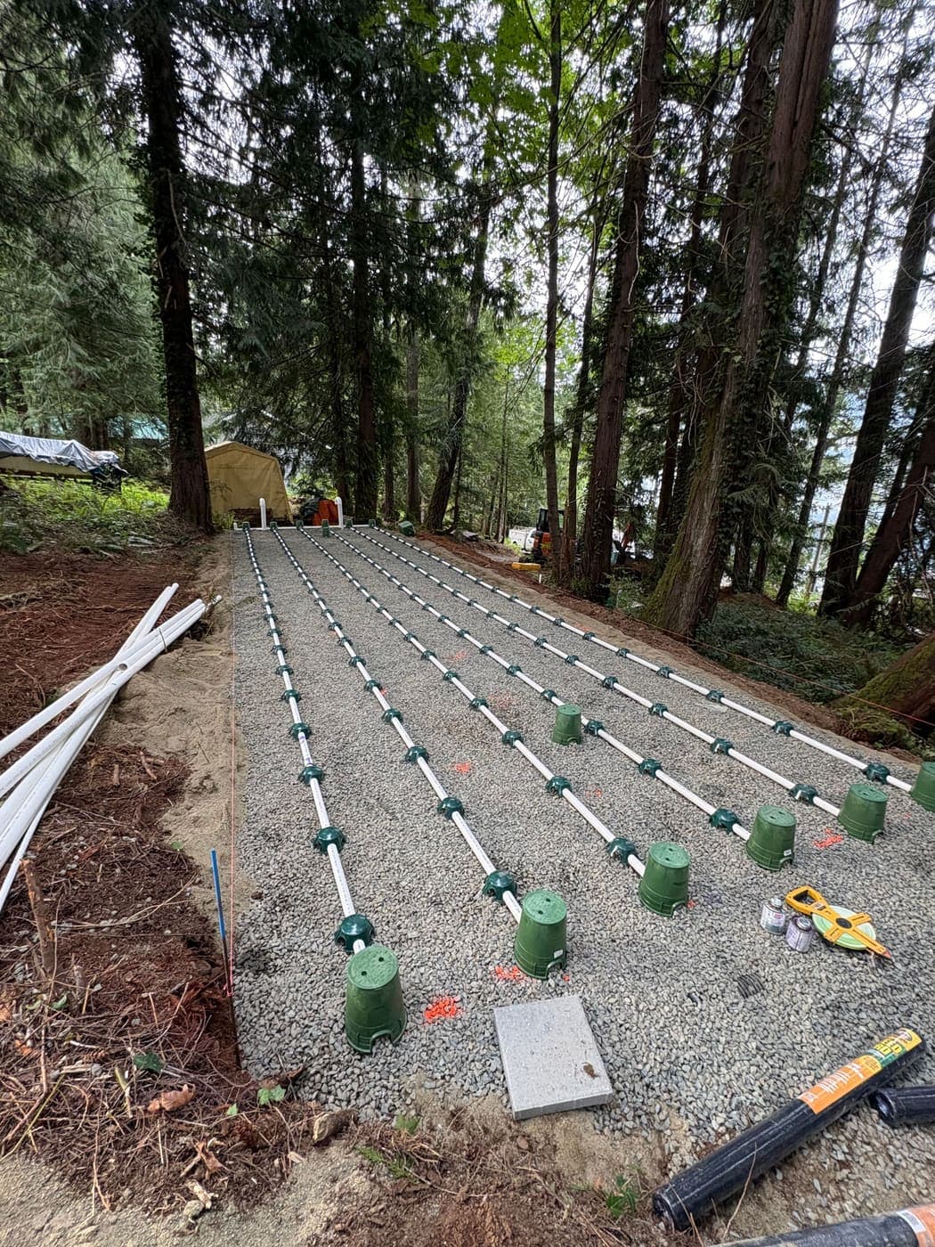
  • Six pressure laterals over 30 cm of specification sand, 108 orifices under shields, four observation ports and passive vent runs, then a field commissioning visit to prove the panel setpoints, squirt height and distribution.

What was the outcome?

The system was installed and commissioned, with a field commissioning visit to verify the panel, dosing setpoints and distribution before the certification package was completed for the owner.
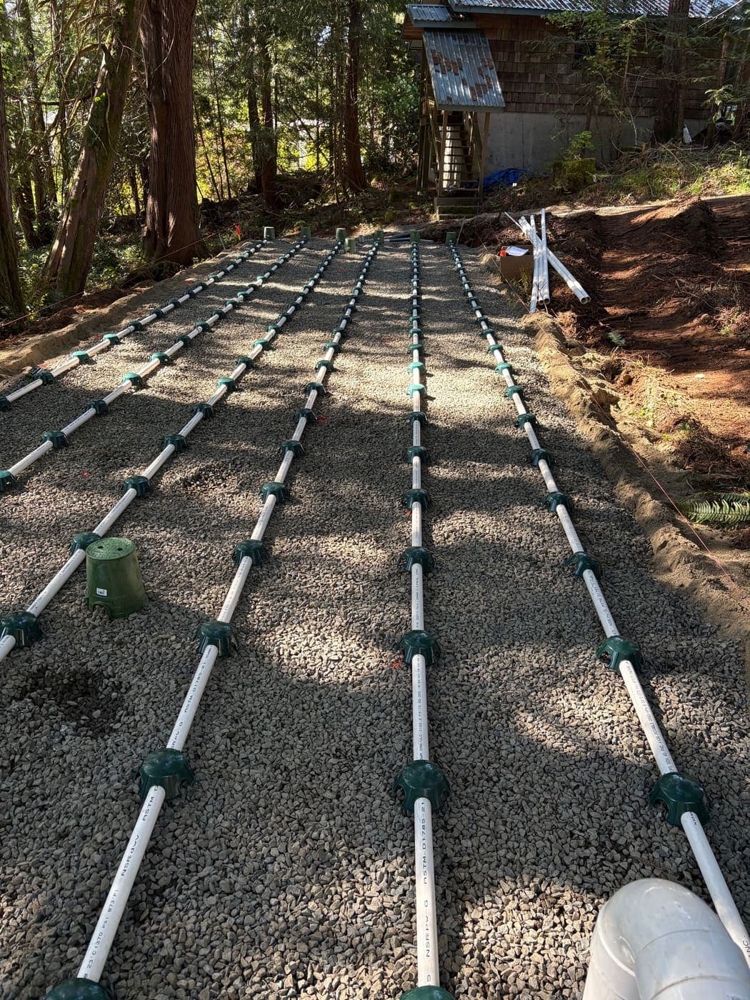
Six white PVC pressure distribution laterals laid in washed pea gravel across a sand lined bed, each orifice covered by a green shield
Pressure laterals in washed aggregate — every orifice under a shield, spaced to distribute evenly end to end.
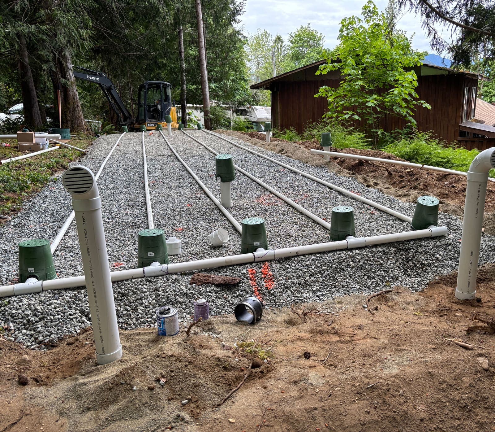
Sand lined dispersal bed with pressure laterals and green observation port risers standing above the aggregate in a forested lakeside setting
Observation ports at the basal and infiltrative surfaces, so the bed can be inspected for the life of the system.
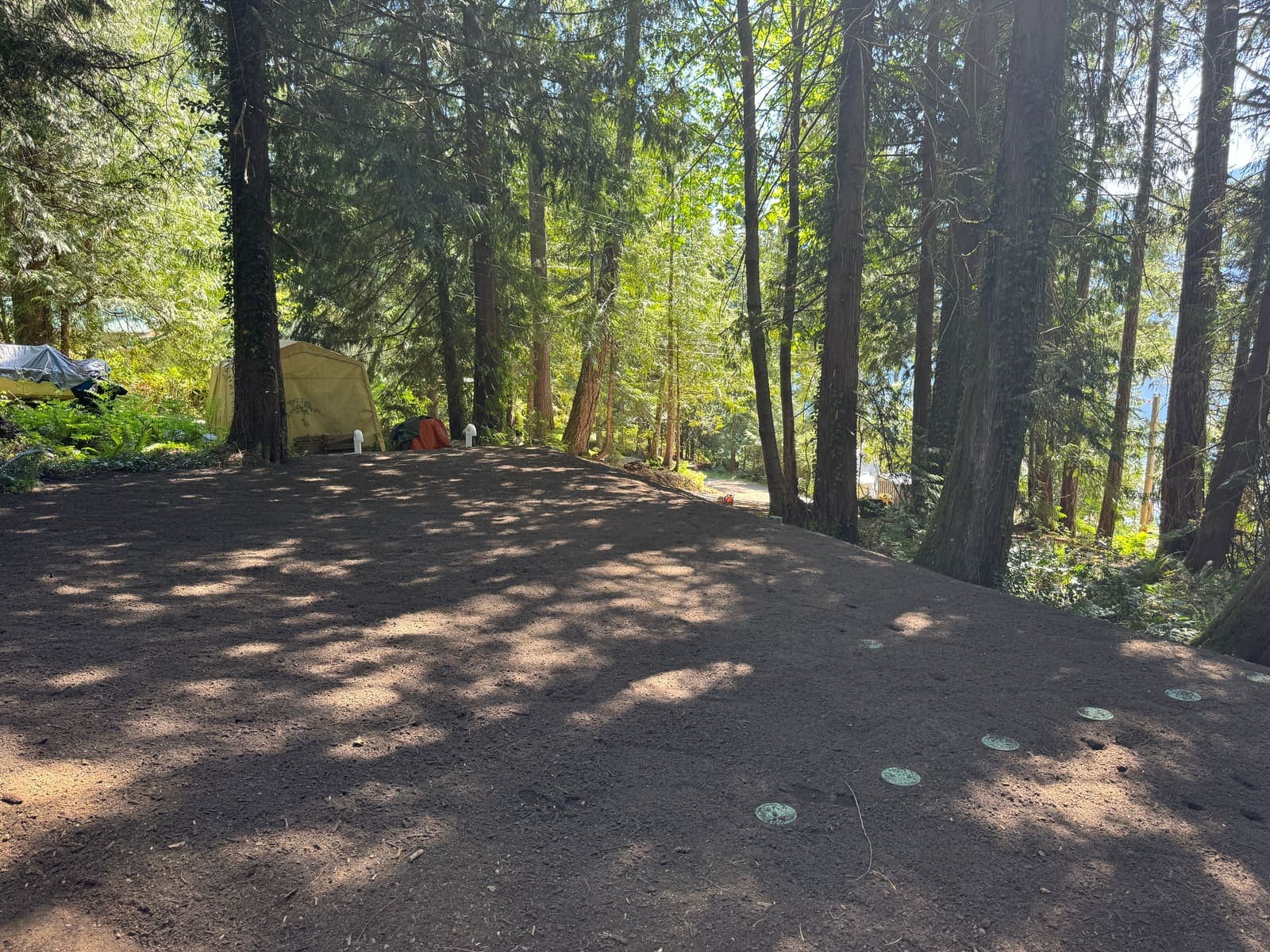
Completed sand lined dispersal field covered with soil and graded flat beneath tall conifers, with only the port lids visible at the surface
Covered and graded. Once it is finished, a well-designed bed mostly disappears.

More about Residential Septic System Design

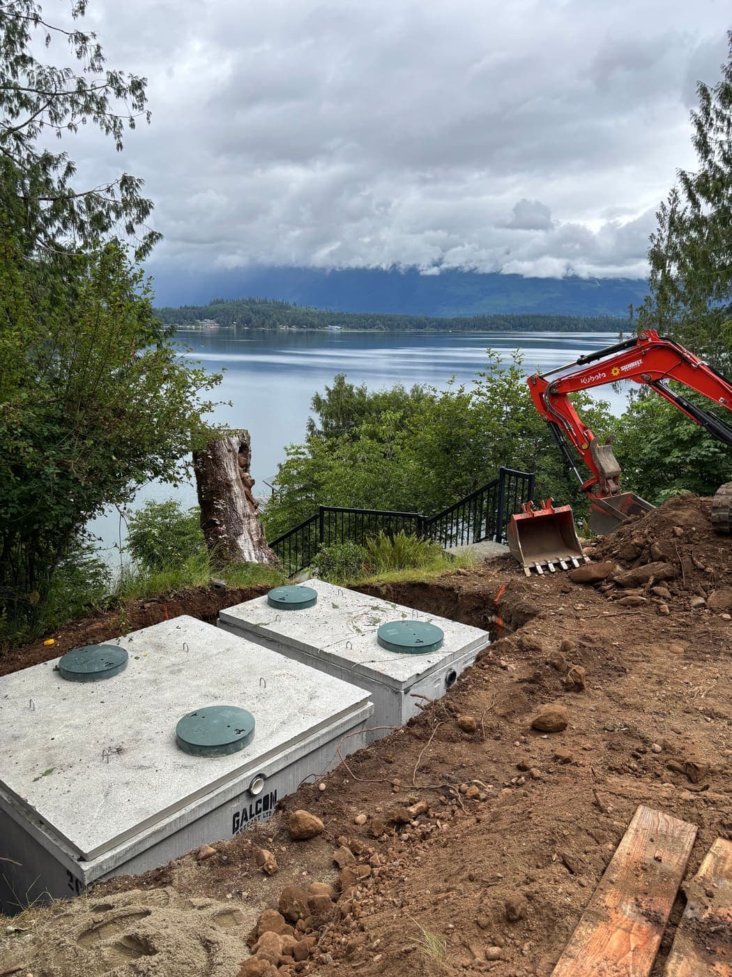
Two concrete septic tanks with green riser lids set into an excavation on a lakeside bench, with a red excavator alongside and forested mountains across the water

Project 02

Type 2 amended-sand bed with a setback departure to a drinking-water lake

Location
Sproat Lake area, rural Alberni Valley
System type
Type 2 Eljen GSF bed with biochar-amended sand and a crushed oyster shell polishing layer, timed dosing
Timeline
Test pits spring 2026; design filed early June 2026; installed the same month; Letter of Certification submitted July 2026.

A reputable septic installation company brought Pacific Rim Wastewater Solutions in as the designer on a four-bedroom lakeside home where the dispersal area sat close to a freshwater body used as a surface source of drinking water. The setback departure ruled out a prescriptive design. The answer was a performance-based Type 2 system with an engineered media stack that treats the effluent before the ground has to.

What made this site difficult?

  • A setback departure to a freshwater receiving body used as a surface source of drinking water, which required a performance-based justification rather than the standard prescriptive setback.
  • Amended sand media was required to achieve Type 2 treatment, so although the site carried over a metre of native soil, part of it had to be excavated to build the engineered media stack beneath the infiltrative surface.
  • A limited-access site on a steep slope — machine access, material delivery and the sequence of construction all had to be planned around the grade rather than assumed.
  • Nutrient loading toward a lake used for recreation and drinking water — nitrogen, phosphorus and pathogen attenuation all had to be demonstrated, not assumed.

How was it solved?

  • Designed as a Type 2 system using Eljen GSF modules to achieve secondary treatment: a 16.0 × 2.0 m bed of 24 modules, end-fed in a single zone at 1,600 L/day design flow, timed-dosed so loading stays even.
  • Built an engineered media stack under the infiltrative surface — 15 cm of specification sand, 30 cm of sand amended with 15 per cent biochar by volume, then a 15 cm crushed oyster shell polishing layer for additional treatment before the effluent ever reaches native soil.
  • Ran the full performance-based justification a P.Geo. is qualified to seal: vertical separation, Payne & Ralston water-table mounding, organic loading rate, and a nitrogen, ammonia, phosphorus and pathogen mass-loading screen taken all the way to the lake boundary. Every check passed, and the calculations remain on record with Pacific Rim Wastewater Solutions.
  • Specified a downgradient observation port as a key component of the design — it allows long-term monitoring of groundwater quality downgradient of the bed, before it reaches the lake.
  • Carried a contingency: if monitoring ever shows the amended sand media bed is not performing adequately, a permeable reactive barrier can be added downgradient rather than rebuilding the system.
  • Multiple site visits were incorporated to overcome on-site challenges during construction, alongside monitoring wells and a low-disturbance installation method specified for the excavator operator.
  • The as-built record, manuals and maintenance schedule were archived and linked to a sticker on the control panel, so anybody on site can retrieve the full design and construction record without a records search.

What was the outcome?

The system was built, commissioned and certified, with the maintenance and effluent sampling schedule set and reminders in place. The downgradient observation port gives the owner a way to demonstrate performance over the life of the system rather than assuming it.

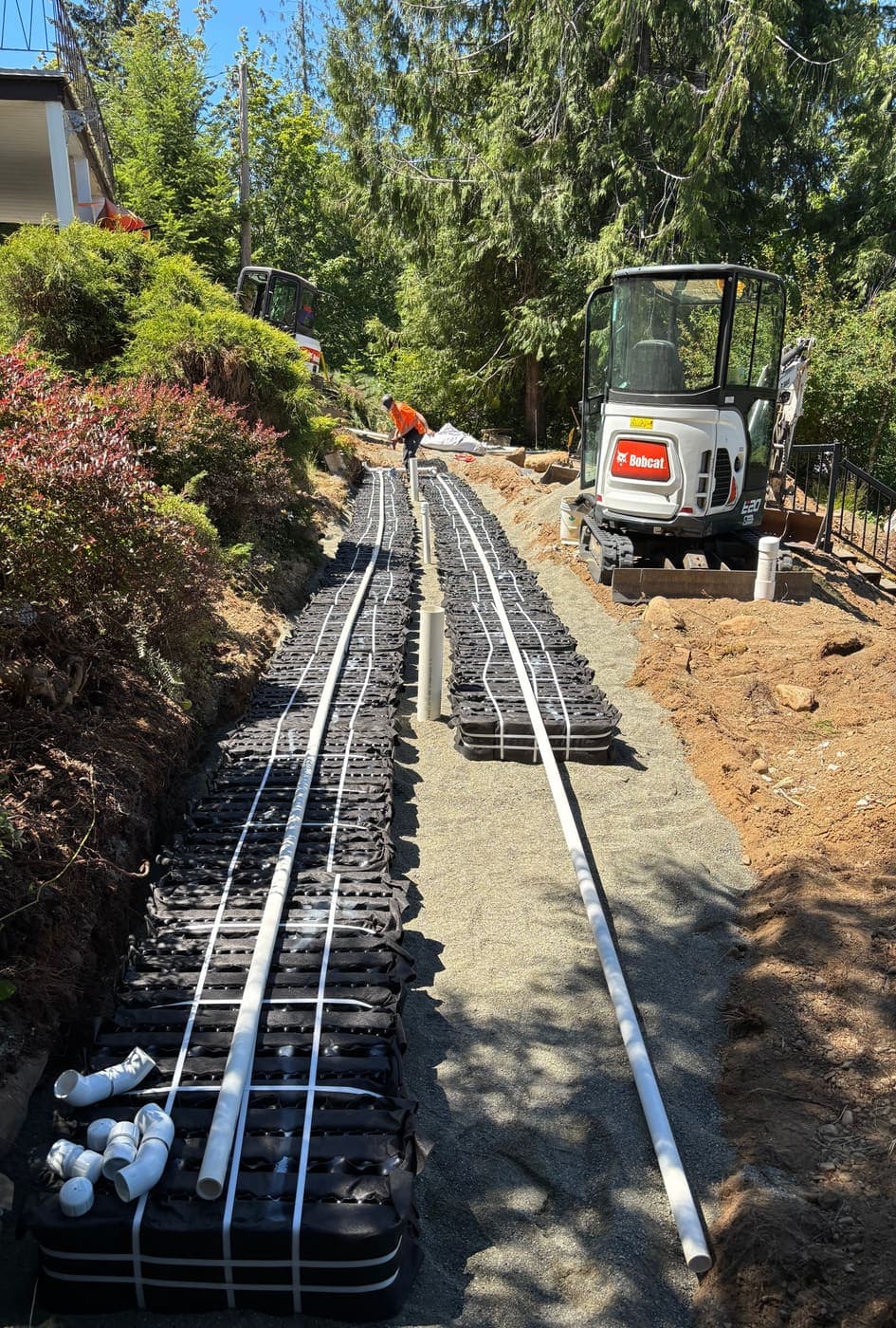
Rows of black Eljen GSF dispersal modules laid in a narrow bed on a sloped property, with white PVC distribution pipe running the length and a compact excavator working alongside
Eljen GSF modules laid out in a long, narrow bed — the shape the site allowed, and the treatment the lake required.

More about Residential Septic System Design

Sand lined seepage bed under construction with white PVC pressure laterals, green observation port risers and two tall passive vent risers, an excavator parked at the head of the bed

Project 03

A second wide sand lined bed with passive ventilation in a sensitive lake environment

Location
Sproat Lake area, rural Alberni Valley
System type
Type 1 sand lined bed, micro-time-dosed pressure distribution with passive ventilation
Timeline
Design filed April 2026; installed 1 June 2026; field commissioning and certification 3 June 2026.

On a sloped acreage above the lake, the site again called for a sand lined bed wider than the 3 m maximum the Standard Practice Manual provides for. The design carries passive ventilation across the full width of the infiltrative surface, and the system was proven by functional testing at commissioning rather than assumed to work once covered.

What made this site difficult?

  • A bed wider than the 3 m maximum width the Standard Practice Manual provides for, which means ventilation of the infiltrative surface has to be designed rather than inherited from a standard detail.
  • A sensitive lake environment downslope, where the consequence of an underperforming bed is borne by the receiving water rather than only the owner.
  • A pump chamber on a sloped site needs ballast against flotation.
  • Distribution across a wide bed has to be even end to end, or the effective infiltrative area is smaller than the drawing claims.

How was it solved?

  • Passive ventilation carried across the full width of the bed, so the infiltrative surface stays aerobic despite a footprint wider than the standard detail contemplates.
  • Ran a full functional test at commissioning: pump cycles, float and panel test, squirt test and a leak check. The squirt height came in at about 6 ft with even distribution across all five laterals.
  • Set the primary timer-enable level so the chamber carries enough liquid ballast for anti-flotation on the slope — a deliberate field decision, made on site and written into the record.
  • Kept redundant high-level-alarm and pump-off floats as mechanical backups behind the pressure sensor, so a single sensor fault cannot silently disable protection.
  • Observation ports set at the basal and infiltrative surfaces so the bed can be inspected for the life of the system, with as-commissioned dosing values and panel setpoints recorded in the certification package.

What was the outcome?

The system was tested, accepted and certified with a full written record of what was actually installed, along with the maintenance package handed to the owner.

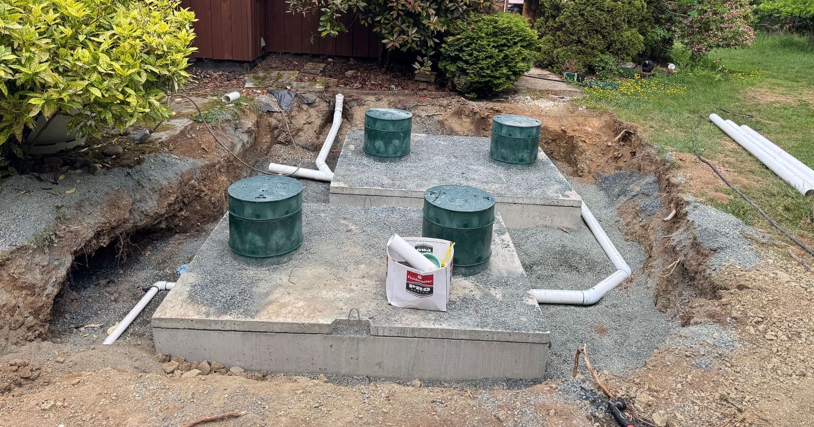
Concrete tank lids with four green access risers set on a levelled gravel pad in an excavation beside a house, with white PVC pipework running to and from the tanks
Tank access risers brought to grade — level sensing, floats and the effluent filter all have to stay reachable.

More about Homeowner Installation Oversight

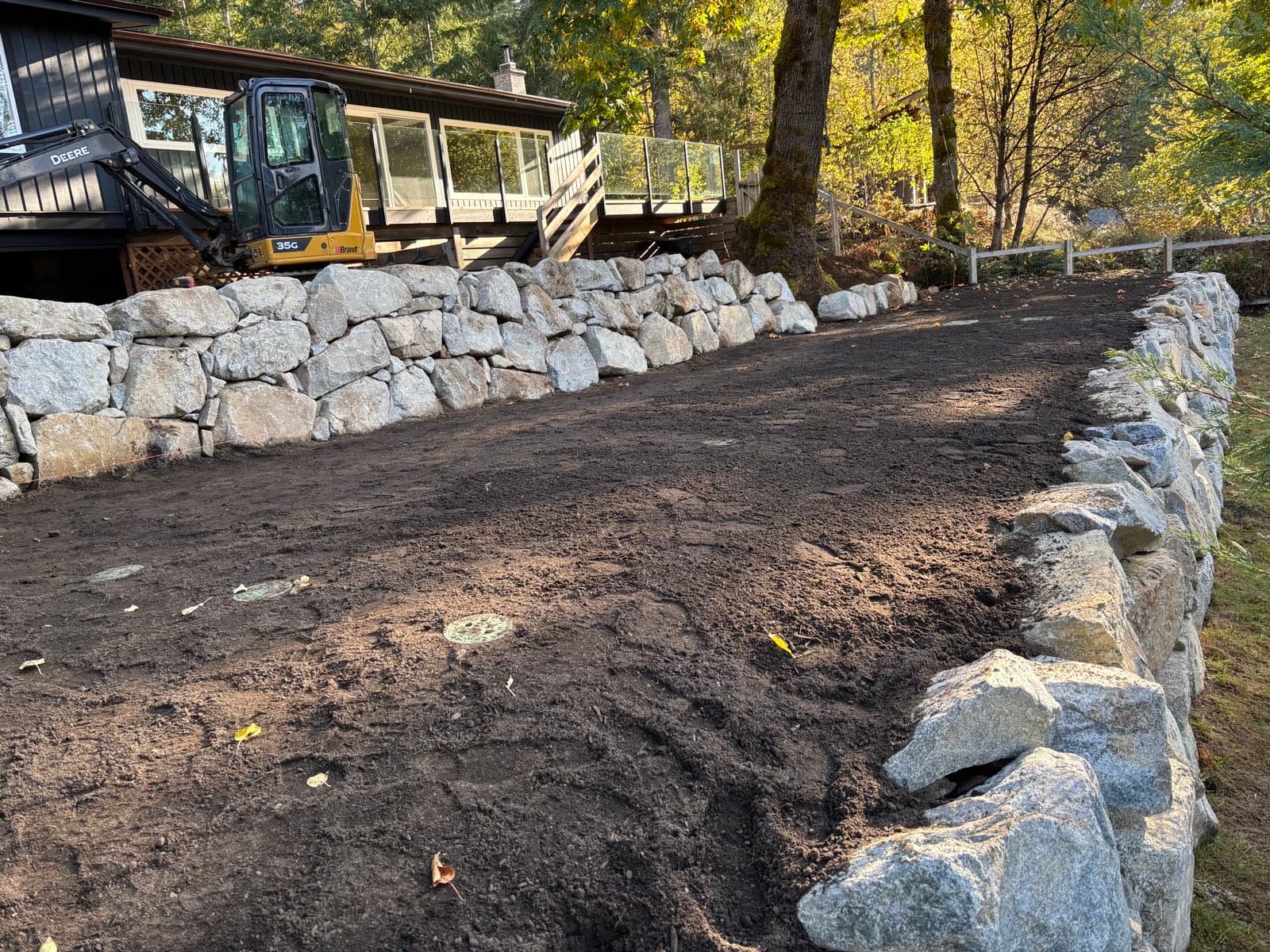
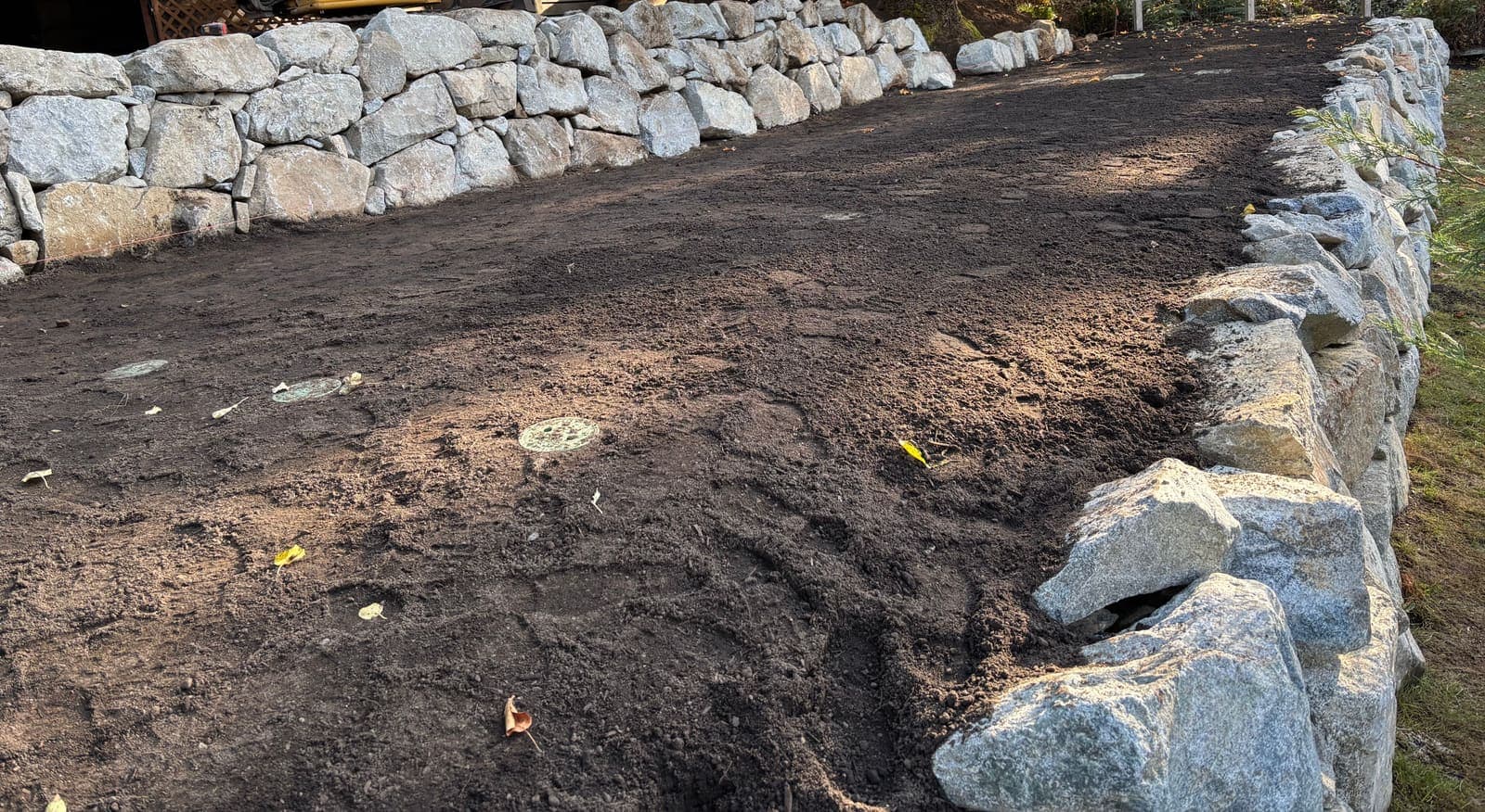
Completed terraced dispersal bench on a sloping property, bounded by two courses of granite armour rock retaining wall, with graded soil cover and observation port lids visible at the surface and a compact excavator beside the house

Project 04

Pressure distribution bed built into a terraced rock slope

Location
Rural Alberni Valley
System type
Type 1 pressure-distribution seepage bed on an engineered terraced slope

This site had the soil for a conventional pressure-distribution bed but not the grade. Rather than push the system onto poorer ground, the dispersal area was created by terracing the slope behind granite armour rock retaining walls, producing a level bench that carries the bed at the correct elevation above the tank nest.

What made this site difficult?

  • No naturally level area large enough to carry the dispersal bed at a workable elevation.
  • A working slope that had to remain stable in the long term once loaded with a dispersal bed, cover soil and the water it disperses.
  • Tank nest, transport main and bed all had to be sequenced on a grade, in a yard tight against the house.

How was it solved?

  • Terraced the slope behind granite armour rock retaining walls to create a level bench sized for the dispersal bed, rather than relocating the system onto ground less suited to it.
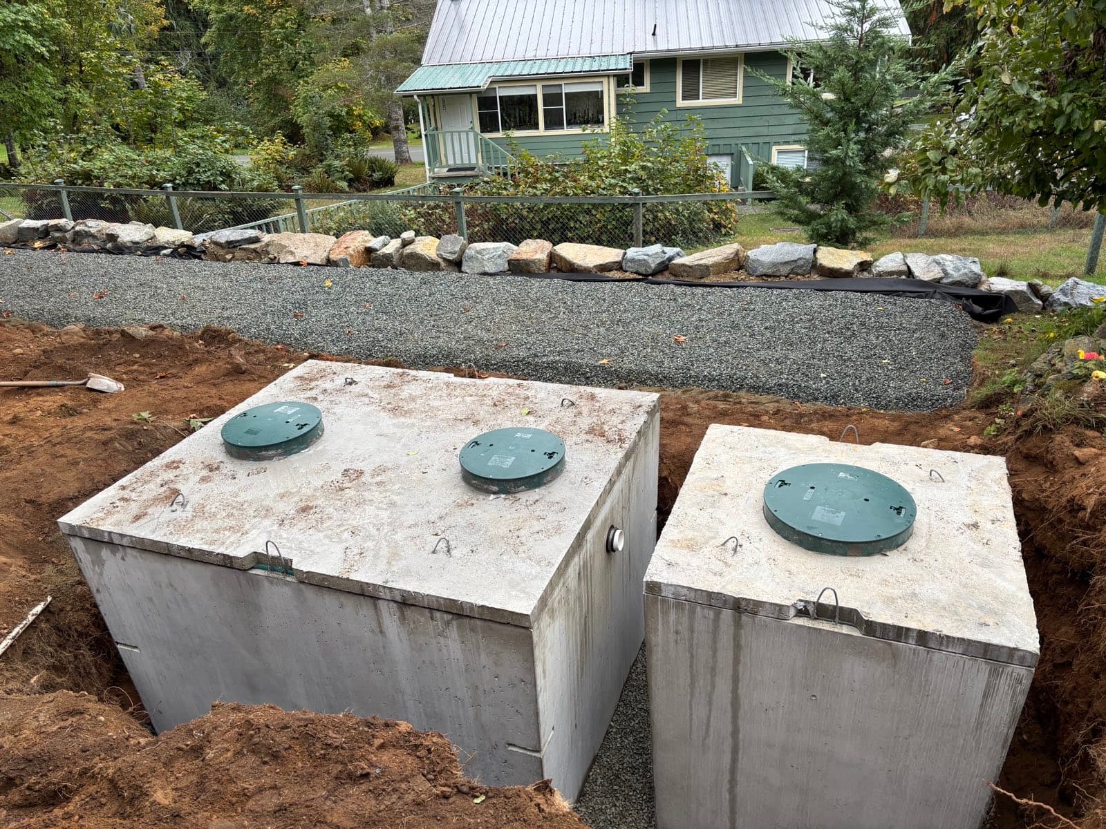
  • Set a twin concrete tank nest into the slope below the bed, with risers brought to grade so the effluent filter and level controls stay serviceable.
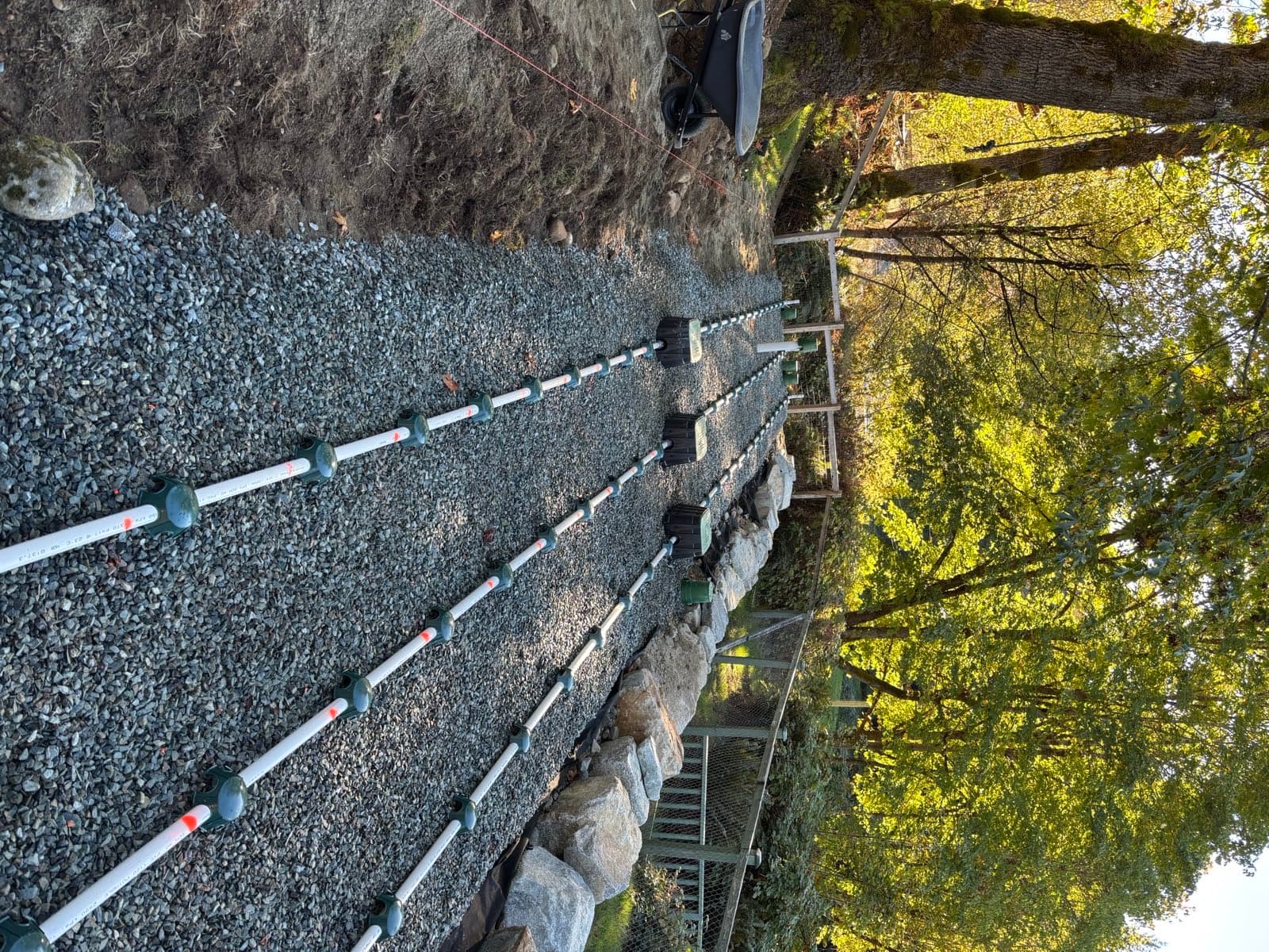
  • Built a pressure-distribution seepage bed on the terrace — laterals in washed drain rock, every orifice under a shield, distribution proven end to end before the bed was covered.
  • Observation ports and valve boxes set so the bed and the distribution network can both be checked without excavation.
  • Finished ground graded and reinstated over the completed bench, leaving a usable yard rather than a construction scar.

What was the outcome?

The completed system sits on ground that did not exist before construction. The terraced bench carries the dispersal bed at the elevation the design required, and the finished surface reads as landscaping rather than infrastructure.

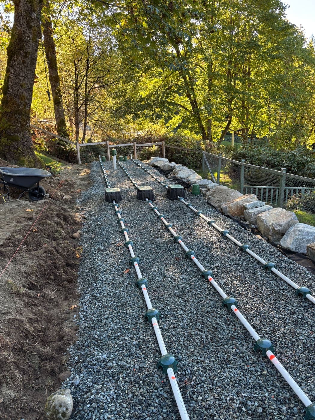
Three white PVC pressure distribution laterals with orifice shields running the length of a washed drain rock bed on a terrace, with valve boxes at the head and a granite rock retaining wall along one edge
Pressure laterals in washed drain rock, orifice shields in place, valve boxes at the head of the bed.
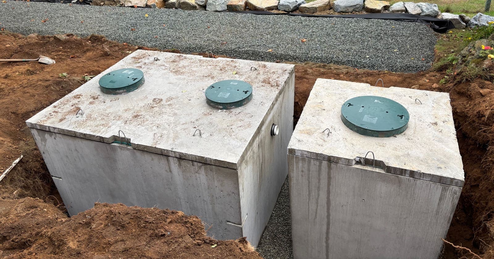
Two large concrete septic tanks with green access lids set side by side in an excavation below a rock retaining wall and gravel terrace, with a house behind
Twin tank nest set below the terrace, risers brought to grade so the filter and controls stay reachable.

More about Residential Septic System Design

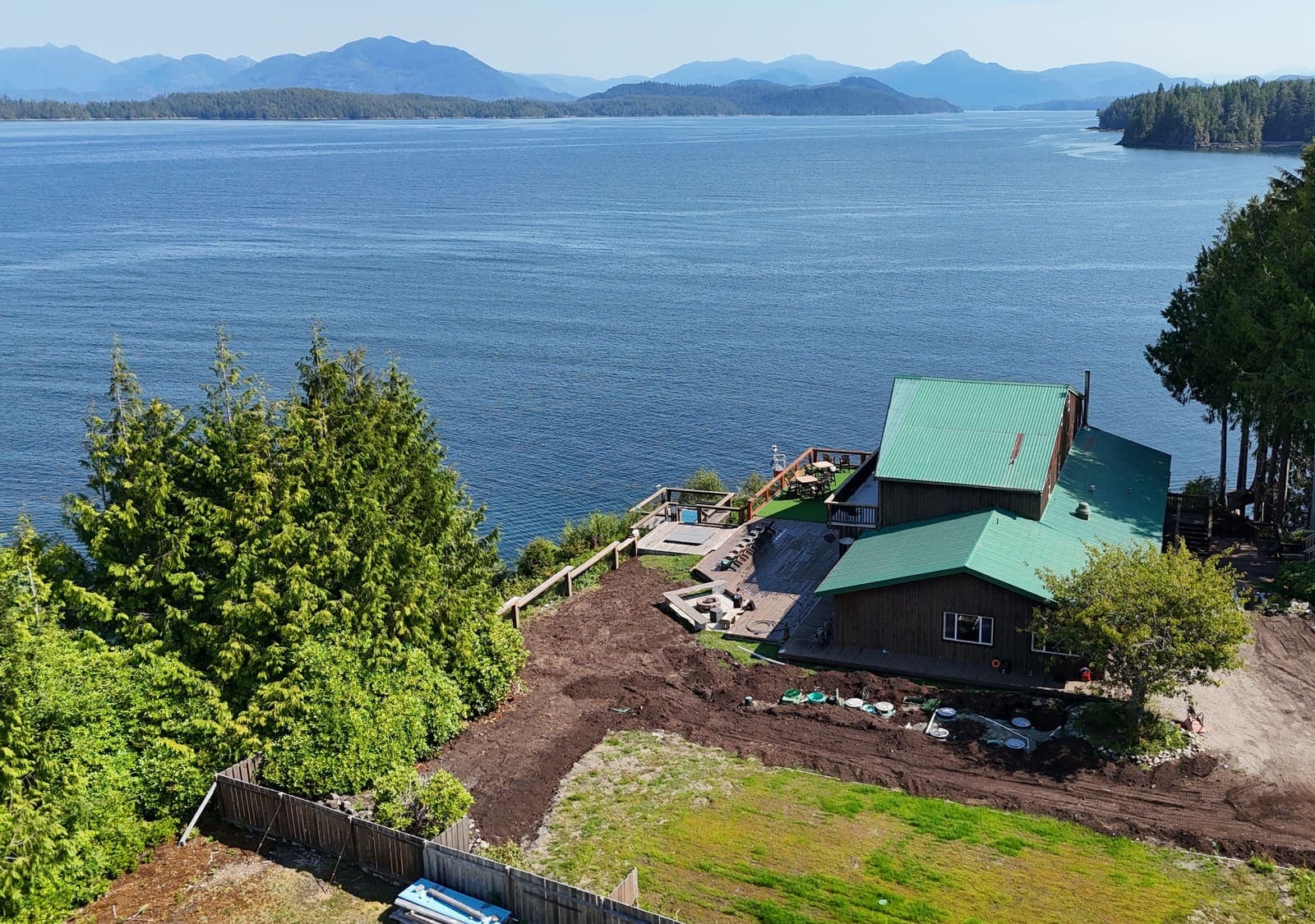
Aerial view of a remote west coast waterfront lodge with a green metal roof, freshly excavated ground for a septic installation in the foreground and forested islands across a calm inlet

Project 05

Commercial system for a remote boat-access resort

Location
A remote boat-access resort near Bamfield, on the outer west coast
System type
Commercial custom design — packaged secondary treatment, UV disinfection and subsurface drip dispersal
Timeline
Site assessment September 2025; filing report issued through 2026; installation underway through mid-2026.

A multi-building resort reachable only by boat needed a commercial-scale onsite system serving a lodge and cabins. Access governed everything: tanks, sand, treatment units and controls all had to reach the site by water. As the project ran, changing client needs and what could actually be supplied to a remote site meant the design was reassessed and adapted rather than delivered once and left.

What made this site difficult?

  • Boat access only. The bulk of the material — tanks, sand, aggregate and equipment — went in on a single large barge trip, and everything afterwards had to come down the inlet in smaller loads.
  • The many smaller parts and follow-up materials came in aboard the MV Frances Barkley, the Lady Rose Marine Services freight vessel that serves Bamfield and Barkley Sound — so a missing fitting is a sailing schedule, not a trip to the supply store.
  • Cabins and service buildings sit in different locations across the site, so pump vaults, treatment units and control panels are distributed rather than collected in one place.
  • Client needs changed during the project, and the design had to be reassessed against what treatment systems and supplies could realistically be delivered to a remote site.
  • Control complexity: pumps split across dedicated branch circuits, motor starters with individual overloads, interlocks between the treatment units and dosing pumps, and cross-site signal runs between pump vaults.

How was it solved?

  • Site assessment and sieve analysis first, then a full commercial custom design filed with Island Health.
  • Specified subsurface drip dispersal — the technology that copes best with a site where treated effluent must be spread shallowly and evenly across irregular ground — downstream of packaged secondary treatment and UV.
  • Adapted the design as the project progressed, reassessing treatment options and sizing against the equipment and materials that could actually be barged to the site, rather than holding to a specification the supply chain could not serve.
  • Designed around where the buildings actually are, and for future adaptability — conduit was run to all areas so the system can be extended or re-controlled later without reopening the site.
  • Worked closely with the electricians to develop control logic and an electrical plan that would accommodate the unique needs of a system this complex, reissued as field conditions and equipment availability changed.
  • Separated pump protection deliberately — each dosing pump on its own branch circuit, its own contactor and its own overload, rather than two motors behind one device, so a degrading pump is actually caught.

What was the outcome?

Construction is underway. The project is included here because it shows the scale, the access constraints and the adaptability the work demands, not because it is finished.

A commercial-scale system going in on a boat-access site. Excavation in the foreground; every component arrived by water.

More about Commercial Septic System Design

What does this work actually look like?

More field photography from Vancouver Island installations. No project detail is attached to these — they are here to show the standard of workmanship a sealed design and an attended install are supposed to produce.

Two concrete septic tanks with green access lids set side by side in a fresh excavation, backfill gravel and a rock retaining wall behind them
A two-tank nest set and levelled before backfill.
Three long white PVC pressure distribution laterals with green orifice shields running the length of a gravel dispersal bed on a wooded slope
Pressure distribution laterals running the full length of a dispersal bed.
A completed dispersal field covered with dark topsoil and graded flat between two granite rock walls, with observation port lids flush at the surface
The same kind of site once it is covered, graded and handed back.

Questions about these projects

Why are no client names or addresses shown?

Because a septic system is private information about someone's home. Every project on this page is real and every technical detail comes straight from the project record, but locations are generalised to a district and no client name, address, legal description or coordinate is published. Clients are told the same thing before any photo is used.

Are these projects typical of the work?

They are typical of the harder end of it. Straightforward sites — deep soil, gentle grade, room to spare — do not generate interesting case studies, and they are a large share of the work. The projects here were chosen because they show what happens when the ground does not cooperate.

Can I see the design report for a system like mine?

Not another client's, but Jordan will walk you through what a design report contains, what Island Health receives, and what you will be given at the end. Call (250) 735-5154 or send a note through the contact page.

Is your site one of the difficult ones?

Steep ground, shallow bedrock, a small lot, a lake or stream nearby, or an existing system that has stopped working — those are the sites worth a conversation before anyone quotes you a number. Residential designs are typically delivered within a week of the site assessment.

Call (250) 735-5154Email Jordan